Digital Bidirectional DC/DC Converter Controlled by DSP
With the rapid development of information technology, digital technology has also played a huge driving role in the development of power electronics technology. With the development of power electronics technology and digital control technology, more and more digital control switching converters are being put into use. However, there are still some issues that need to be addressed in high-frequency PWM converters.
With the increasing improvement and maturity of digital signal processing technology, it has shown more and more advantages, such as being convenient for computer processing and control; Avoid distortion and distortion in the transmission of analog signals; Reduce interference from stray signals; Facilitating the implantation of self diagnosis, fault tolerance, and other technologies. In the early days of computers entering the field of power electronics technology, they only completed auxiliary functions such as monitoring and display, achieving system level control. However, with the development of digital technology, computers have been applied to control circuits. Digital controllers specifically designed for PWM converters are becoming increasingly popular due to their low power consumption and insensitivity to changes in analog circuit parameters. They can be easily connected to digital systems and enable the implementation of comprehensive and mature control schemes. Applications in this area include microprocessors for voltage regulation modules (VRMs), audio amplifiers, portable electronic devices, and more.
Digital controlled power electronic devices use digital controllers instead of analog hardware circuits for PWM control, and achieve power conversion through fast switching of switches. The digital control of digital power converters based on duty cycle quantization has many advantages over traditional analog control. Digital filters are used for dynamic adjustment. If their sampling frequency is set to be equal to the sampling frequency of the power converter, the quantized duty cycle digital controller can operate at any switching frequency without further compensation. By modifying the weight coefficients, the dynamic adjustment characteristics can be easily changed. Meanwhile, basic digital controllers can easily implement special functions such as output current limiting and soft start.
This article is based on a summary of the development history of digital control and summarizes the advantages of digital control. Through the analysis of the working principle of the full bridge isolated bidirectional DC/DC converter, from the perspective of simplifying the hardware circuit, all control functions are centralized and implemented by software. In the experiment, both voltage adjustability and voltage regulation output are met. At the same time, the bidirectional operation of the circuit is also implemented by software, which enables constant current charging of the battery. The digital controller used in the experiment is TMS320LF2407, and the entire control system is a digital control platform for the developed universal power electronic device.
1 Basic structure and working principle of digital control bidirectional DC/DC converter
With the development of technology and production, the demand for bidirectional DC/DC converters is gradually increasing, mainly including applications such as DC uninterruptible power supply systems, aerospace power systems, electric vehicles, DC power amplifiers, and battery energy storage.
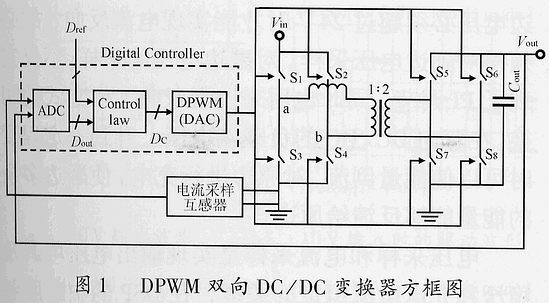
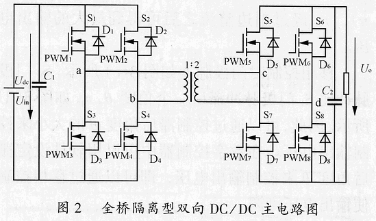
The basic structure of a digital pulse width modulation (DPWM) bidirectional DC/DC converter is shown in Figure 1. This article adopts a full bridge isolated bidirectional DC/DC converter as the main circuit structure of the experimental device.
The controller consists of an analog-to-digital converter (ADC), a DPWM control module, and a discrete control module. The ADC module discretizes the adjustable quantity (typically the sampled output voltage Vout), DPWM converts the control information into a PWM pulse width signal, and the discrete control center performs calculation and modulation of the feedback quantity.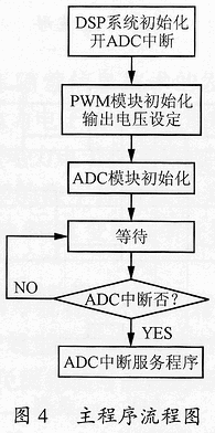
Below is a brief analysis of the working principle of the bidirectional DC/DC main circuit
1.1 Primary side to secondary side discharge
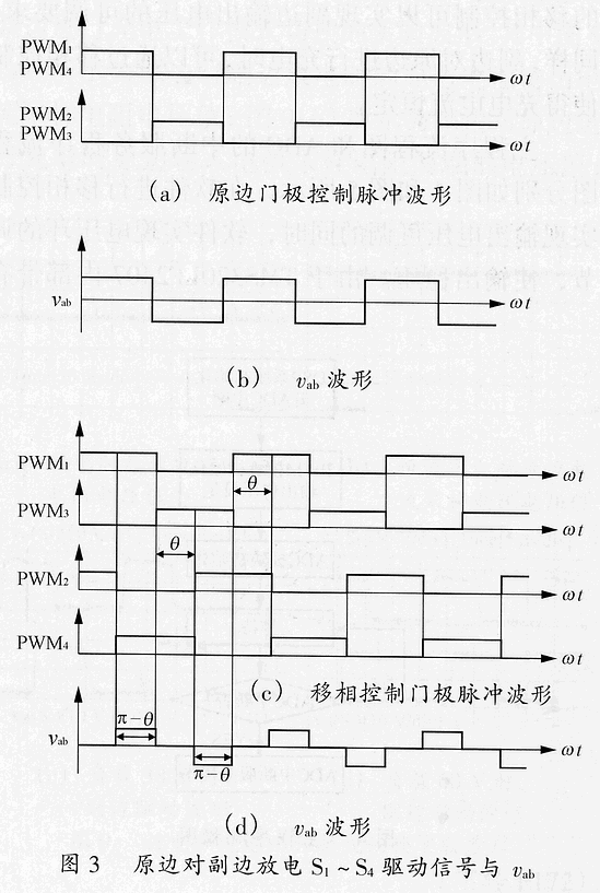
When fully modulated, the driving waveforms of S1-S4 are shown in Figure 3. The waveforms in the figure do not take into account the dead zone, indicating that the switching transistor is an ideal device. In Figure 3 (a), PWM1 and PWM4 are in phase without phase shift. At this time, the output voltage of the secondary side is the highest. If losses are not considered, the output voltage of the secondary side is nVin, which is the output under full modulation. At this time, the secondary side is rectified by the main switch anti parallel diode, which is uncontrolled rectification. The switching function of the primary side is equivalent to modulating the input signal into an AC square wave signal, while the secondary side diode demodulates the signal into a DC voltage output. At this time, there is no pulse width gap, and the secondary side pulse is blocked. The input signal Vab on the primary side of the transformer is shown in Figure 3 (b). Since the pulse widths of S1, S4, S2, and S3 are all T/2T (switching period), the positive and negative half waves of Vab have a duration of T/2 (i.e. π). After rectification on the secondary side, Vab can obtain the maximum output voltage.
During phase shift control, the gate pulse is shown in Figure 3 (c). The S4 gate pulse lags behind the S1 gate pulse by an angle θ, and Vab is shown in Figure 3 (d). Therefore, the output voltage can be controlled by adjusting the magnitude of the hysteresis angle θ. In digital controllers, software can be used to set the hysteresis angle θ to control the output voltage, which can be adjusted through phase shifting control.
1.2 Charging from the secondary side to the primary side
At this point, as shown in Figure 3, as long as the driving signals of S5 to S8 are exchanged with the driving signals of S1 to S4, Vab can be replaced by Vcd. There are also two situations: full modulation and phase shift control. However, in general, constant current charging is required for charging, so this requirement can also be met through phase shift control. The working process of the primary and secondary edges is exactly opposite to that during discharge. I won't go into detail here.
Software Implementation of Bidirectional DC/DC Digital Control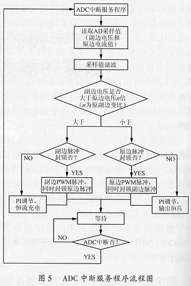
A bidirectional DC/DC converter can achieve bidirectional transmission of energy. Normally, forward discharge requires an adjustable output voltage, while reverse charging typically requires a constant charging current. By controlling the phase shift of S3 and S2, the adjustable output voltage of the secondary side can be achieved. Similarly, when the secondary side charges the primary side, the charging current can be kept constant through phase shift control.
The main program flowchart and the interrupt service program flowchart of the ADC are shown in Figure 4 and Figure 5, respectively. While the software performs phase shift control to achieve adjustable output voltage, the software also adjusts the voltage loop to stabilize the output voltage. Due to the internal ADC module of TMS320LF2407, the output voltage value is sampled and fed back to the DSP's ADC module through voltage LEM. The sampled value is read in the AD interrupt program and then subjected to digital filtering and digital PI adjustment to stabilize the output voltage.
The general charging requirement is constant current charging, so during charging, a feedback current loop is used to PI regulate the charging current on the primary side, achieving constant current charging. In this experiment, the primary power supply is a battery. Due to its voltage of 12V, in order to achieve current reversal and make the diode on the primary side conductive, considering that the transformer's primary and secondary sides have a transformation ratio of 1:2, the secondary side voltage must exceed 24V to achieve current reversal. Therefore, it is necessary to sample the secondary side voltage. The sampling of the secondary voltage not only achieves PI regulation, but also controls the switching of the bidirectional working mode. When the voltage at the load end of a bidirectional DC/DC rises to a certain level, it can reverse the energy and charge the primary side, allowing excess energy from the secondary side to be fed back to the primary side.
Voltage sampling and current sampling are key to achieving adjustable and stable output voltage and constant charging current. The sampled values are digitally filtered and PI regulated in the interrupt service program of DSP. The program performs PI adjustment based on the given output voltage reference value and charging current reference value. When the primary input voltage changes, the secondary output voltage stabilizes at the given value; When the voltage of the secondary load fluctuates, the phase shift can also be adjusted based on the given current reference to control the charging current value of the primary side. The digital PI regulation adopts incremental PI control, and its system diagram is shown in Figure 6. Due to the powerful computing power and EV (Event Manager) module of DSP, PWM signals can be easily obtained. Therefore, the hardware part can be greatly simplified, and the control circuit part can be completely omitted and replaced by software, that is, software can implement PI calculation control and PWM signal generation. However, considering the security issues of DSP, optocoupler isolation is necessary.

