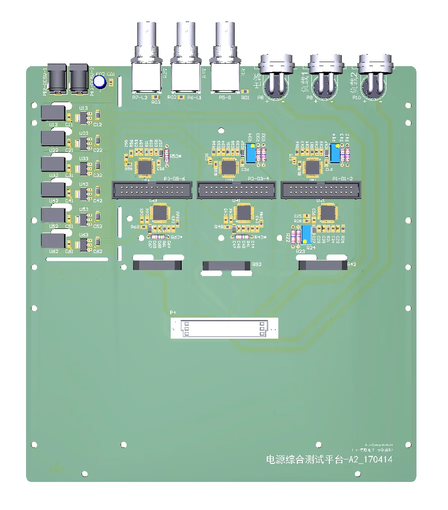

Measurement Instrument Design Based on MAX1447 / MAX1448
The MAX1447/1498 is a 4.5‑digit analog‑to‑digital converter with built‑in LED digit‑tube driver. No external crystal oscillator or clock synchronization is required, and its gain drift is less than 1 ppm. It features simple peripheral circuitry and is suitable for digital multimeters, multi‑function meter heads and similar circuits. Based on this IC, we have designed a multi‑function test box supporting high‑current and high‑precision voltage measurement. The system block diagram is shown below.
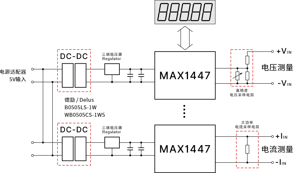
multi‑channel voltage & current measurement, dual‑channel isolated DC‑DC powering MAX1447
DC-DC Module Selection Requirements
DC-DC module selection shall comply with the electrical parameters of the MAX1447. According to the IC datasheet, its supply voltage range is 2.7 V‑5.25 V. The chip has wide voltage tolerance and is insensitive to power‑supply fluctuation. While the chip itself consumes very little power, the LED digit‑tube driver accounts for most power consumption. It is therefore necessary to calculate the total power required by the front‑end power supply and reserve adequate power derating. 1 W rated isolated power modules are recommended.
The post‑DC‑DC regulator (three‑terminal regulator) is optional. For cost‑sensitive designs, conventional three‑terminal regulators can be adopted. Switching regulators are preferred for higher conversion efficiency. Recommended device list is shown below.
PCB Layout Requirements
PCB routing and layout directly affect the measurement accuracy of the final circuit. Special attention shall be paid to ground‑plane arrangement; voltage drop across ground traces cannot be ignored.