

What Is a Linear Regulated Power Supply & Its Characteristics
Based on the operating state of the pass transistor, regulated power supplies are generally classified into two categories: linear regulated power supplies and switching regulated power supplies. Besides, there is another type of miniature power supply built with Zener diodes.
A linear regulated power supply refers to a DC regulated power supply whose pass transistor operates in the linear region. To elaborate on the linear operating state of the pass transistor: the variable resistor RW (illustrated in the analysis below) delivers continuously adjustable resistance, which represents a linear characteristic. In contrast, the switching transistor (named differently in switching power supplies) only works in two discrete states: ON state with ultra-low resistance and OFF state with extremely high resistance. Clearly, transistors running in switching mode do not feature linear characteristics.
Linear regulated power supplies are an early generation of DC regulated power supplies. Their core characteristics are summarized as follows:
- The output voltage is always lower than the input voltage;
- Fast transient response and low output ripple;
- Low operating noise;
- Relatively low power efficiency (LDOs, or Low-Dropout Regulators, were developed to solve the low-efficiency pain point);
- Severe heat generation (especially for high-power variants), which indirectly introduces thermal noise to the whole system.
Working Principle
We first explain the voltage regulation mechanism of linear power supplies with schematic Figure 1. As shown below, the variable resistor RW and load resistor RL form a voltage divider circuit, and the output voltage formula is defined as:
Uo=Ui×RL/(RW+RL)
According to this formula, adjusting the resistance value of RW will change the output voltage.Note that the output Uo does not vary linearly if only RW is adjusted independently; the linear relationship holds only when RW and RL are analyzed as a whole.Another key detail: the tap of RW is drawn on the right side instead of the left. Though this layout makes no mathematical difference to the formula, it visually reflects the sampling and feedback mechanism. Almost all commercial power supplies adopt sampling-feedback control; feedforward control is rarely used and only serves as an auxiliary compensation measure when applied.
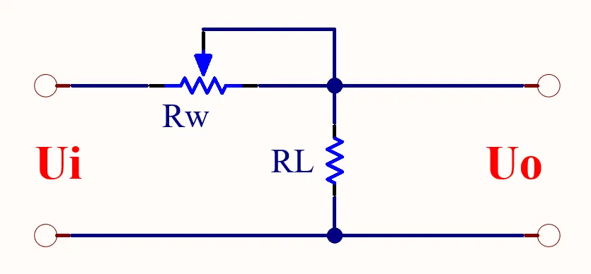
Next, replace the variable resistor RW in Figure 1 with a bipolar transistor or MOSFET pass element. By detecting the real-time output voltage and dynamically adjusting the equivalent resistance of this semiconductor device, we can stabilize the output voltage at a fixed value. This transistor/MOSFET used for voltage regulation is named the pass transistor.
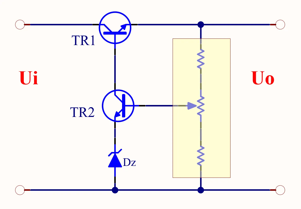
As shown in Figure 2, the pass transistor is connected in series between the input power source and the load, so this topology is called a series linear regulated power supply.Correspondingly, parallel linear regulated power supplies connect the pass element in parallel with the load to stabilize output voltage. The classic reference voltage regulator TL431 is a typical parallel regulator.The "parallel" characteristic works by shunting current (similar to the Zener diode in Figure 2) to stabilize the emitter voltage of the amplifier tube. The schematic may not show the parallel structure at a glance, but its operating principle is inherently parallel.Special reminder: the Zener diode here works within its non-linear breakdown region, so a power supply relying solely on Zener diodes is categorized as a non-linear power supply. We will attach a simplified intuitive schematic later for easier understanding.
Since the pass transistor acts as an equivalent resistor, current flowing through it generates continuous heat. This heavy heat loss of linear-mode pass transistors leads to low overall efficiency, which is the primary drawback of linear regulated power supplies.Readers may refer to analog electronics textbooks for in-depth theoretical knowledge; this article mainly sorts out core concepts and logical correlations for quick comprehension.
In general, a complete linear regulated power supply consists of four fundamental modules: pass transistor, reference voltage source, sampling circuit, and error amplifier. Auxiliary modules such as protection circuits and startup circuits are also integrated in most designs.The simplified schematic below omits components like filter capacitors. Its working logic: sampling resistors collect the real output voltage and compare it against the reference voltage; the error amplifier amplifies the voltage difference signal to adjust the conduction degree of the pass transistor, thereby maintaining a constant output voltage.
Common Series Linear Regulator ICs
- 78XX series (positive output) & 79XX series (negative output): The suffix XX denotes the fixed output voltage, e.g., 7805 outputs 5V DC.
- LM317 (adjustable positive output) & LM337 (adjustable negative output)
- 1117 low-dropout linear regulators (multiple fixed-output variants): The suffix indicates rated voltage, e.g., 1117-3.3 outputs 3.3V, while 1117-ADJ supports adjustable output.
The KB78xx series power ICs from Delus Power can fully replace the above series of series linear regulated power chips.